Optical Measurement Guidelines for High-Power LEDs and Solid State Lighting Products, Part 1

March 6, 2017
The LED industry is growing rapidly and this naturally brings up an important need for reliable measurements of LEDs and solid state lighting (SSL) products. These measurements often form the foundation for a fair comparison between SSL products from different vendors. Consequently, there is an industry-wide push for standards that ensure accurate and repeatable measurements of optical properties for LEDs and SSL products.
The CIE 127:2007 report from the International Commission on Illumination covers guidelines on how photometric, radiometric, and colorimetric quantities for individual LEDs should be measured in calibration labs. However, the report defers responsibility to manufacturers of LEDs and SSL products to ensure that their equipment measure the optical properties of their products correctly.
The optical performance of LEDs and SSL products can be measured with an integrating sphere. However, standard integrating sphere calibration procedures are not always adequate to accurately measure the optical properties of LEDs due to the high spectral radiant flux in the blue region. The objective of this paper is to introduce appropriate calibration procedures, as well as practical operating guidelines for integrating spheres that are used for the characterization of LEDs and SSL products.
Optical measurement basics
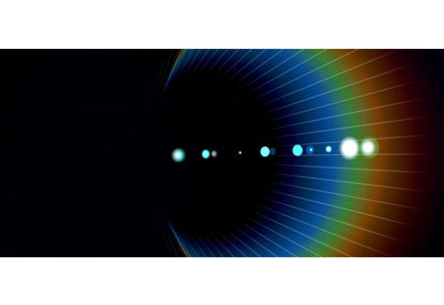
The spectral radiant flux distribution of a light source describes how much radiometric power is emitted by the light source per unit of wavelength across the electromagnetic spectrum. Knowledge of the spectral radiant flux distribution of a light source allows the user to derive other useful optical properties for the light source, including total luminous flux, x-y chromaticity coordinates, dominant wavelength, purity, Correlated Color Temperature (CCT), Color Rendering Index (CRI), peak wavelength, centroid wavelength, and full width at half maximum (FWHM). A list of several common engineering terms, which are regularly used to refer to certain optical quantities derived from the spectral radiant flux distribution, can be found in Appendix A.
For consideration
Performance discrepancies, which are observed for the same SSL product when tested in two different optical measurement systems, are often due to inconsistent calibration procedures and differences in the handling of the device under test. In particular, equipment calibration guidelines used for conventional light sources are not always adequate for LED and SSL product due their high spectral content in the blue region.
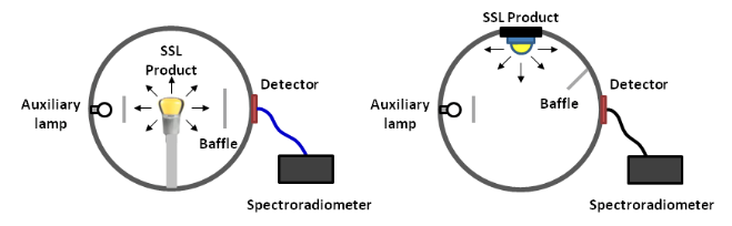
Two different measurement tools are typically used to measure the spectral radiant flux distribution of a light source (see Figure 1):
1. an integrating sphere collects all the lights from a light source placed inside the sphere.
2. a goniometer measures the spectral radiant flux distribution of a light source from many different angles around the source and integrates the results to yield a combined spectral radiant flux distribution for the light source.
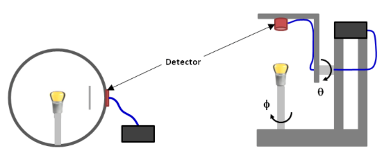
Figure 1
An integrating sphere (left) or a goniometer (right) are typically used to measure the optical performance of an LED or SSL product.
Due to its ease of use, an integrating sphere is often preferred over a goniometer to measure the performance of individual LEDs and SSL products (see Appendix B for a detailed comparison). Therefore, the remainder of this paper discusses recommendations and practical guidelines for optical measurements with an integrating sphere.
Integrating sphere measurements and calibration
There are two different integrating sphere configurations that are typically used to characterize the optical performance of LEDs and SSL products, see Figure 2. A 4π configuration (left) is best suited for an omnidirectional light source while a 2π configuration (right) is best suited for a forward emitting light source.
A complete integrating sphere test system consists of:
• an integrating sphere with appropriate ports and baffles
• reference calibration standards (spectral lamp, reference LED), calibrated by an ISO/IEC 17025 certified laboratory, and appropriate power supplies
• a temperature controlled socket may be required for LED standards to ensure consistent results • Spectroradiometer
• auxiliary lamp and power supply
• computer plus software for calibration and measurement
Integrating spheres can be used to characterize a variety of light sources, including LEDs and SSL products. However, in order to obtain accurate measurement results for LEDs, certain calibration procedures and best practices, as outlined in the remainder of this section, should be followed. In particular, the standard calibration process for an integrating sphere must be tailored to LEDs in order to properly account for their high spectral radiant flux in the blue region.
Figure 2. Typical integrating spheres configurations for optical measurements: an omnidirectional 4π configuration (left) and a forward emitting 2π configuration (right)
Recommended calibration procedure
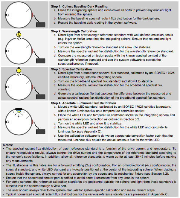
The integrating sphere and corresponding spectroradiometer must be properly calibrated before any LED or SSL product is measured. If the calibration of an integrating sphere is determined to be out of specification, Lumileds recommends the following calibration procedure.
1. Collect baseline dark reading for the integrating sphere. This baseline reading is used to reset the detector of the integrating sphere to “zero”. For this measurement, the sphere system must be sealed from all ambient light. It is best to maintain the same ambient light level (zero or minimum) throughout the measurement process.
2. Wavelength calibration with well-defined wavelength reference standard(s). The integrating sphere must be calibrated first for wavelength accuracy. To do so, light from one or more well-defined wavelength reference standards (e.g. HgAr and HeNe source lamps) should be directed into the integrating sphere.
3. Spectral calibration with broadband spectral lamp. The combined spectral response of the integrating sphere and spectroradiometer must be calibrated to a broadband spectral flux standard, calibrated by an ISO/IEC 17025 certified laboratory. To ensure an accurate response across the visual spectrum, light from a broadband spectral lamp should be directed into the integrating sphere.
4. Absolute luminous flux calibration with a white LED. A typical broadband (incandescent) spectral lamp has very low energy in the blue region and significantly higher energy in the red and infrared regions. This can result in higher amounts of stray light from the infrared region to the visible region of the spectrometer during spectral calibration step (see Stray Light section for more details). Also the low signal-to-noise ratio in the blue region makes the spectral calibration less reliable in the blue region than in the red and infrared regions. A white LED, in contrast, only emits light in the visible spectrum and none in the infrared spectrum. So the amount of stray light that reaches the spectrometer is significantly less. Also, compared to other light sources, white LEDs typically emit a large part of their energy in the blue spectrum. Consequently, a sphere which is calibrated with a broadband spectral lamp may yield incorrect absolute flux readings for (white) LEDs. It is, therefore, important to calibrate the absolute photometric flux reading for the sphere with a white LED standard calibrated by an ISO/IEC 17025 certified laboratory. This reference LED should be mounted onto a temperature-controlled socket to ensure consistent readings. Since this reference LED is typically placed inside the integrating sphere, any absorption losses due to the LED socket and the LED package should be corrected for (as explained in the Absorption Correction for Light Source section) before any measurements are performed.
Each step in this calibration procedure can be further broken down into several sub-steps, as shown in Table 1 (at the end of the article).
Absorption correction for light source and its mechanical fixture
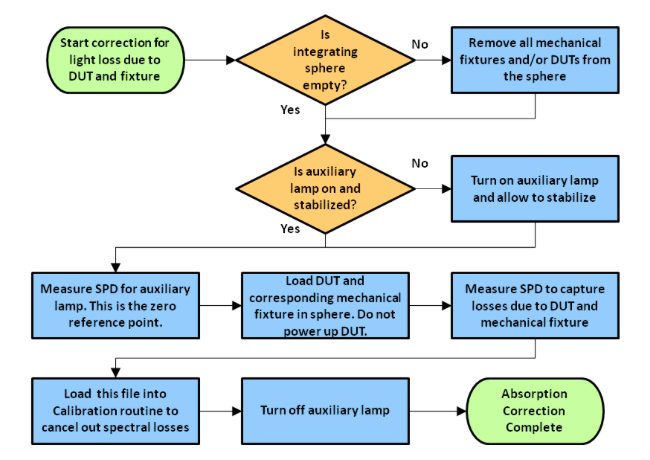
Whenever an object is introduced inside an integrating sphere, the spectral reflectivity of the sphere is changed. This, in turn, affects the overall measurement accuracy of the integrating sphere. So it is important that any absorption losses due to the device under test (DUT) and its mechanical fixture are first accounted for before any measurements are performed.
Absorption correction is typically performed with an auxiliary broadband lamp that is mounted inside the integrating sphere. Light from this auxiliary broadband lamp is used to collect the spectral response of the sphere without and with the DUT and its mechanical fixture. The spectral absorption losses due to the DUT and its mechanical fixture can then be extracted from the difference between the two measured spectral responses. Figure 3 outlines the procedure that Lumileds uses to correct for any absorption losses. This procedure is sometimes also referred to as Substitution Error Measurement. Once the absorption due to the DUT and its mechanical fixture is properly characterized, the integrating sphere is ready to perform actual measurements with the DUT.
It is important to note that the DUT should remain off throughout the Absorption Correction procedure. Also, the auxiliary broadband lamp should be allowed to stabilize before the procedure is started. Finally the procedure should be repeated for any new DUT or mechanical fixture that is placed in the integrating sphere.
Figure 3: Recommended absorption correction procedure
Best practices
Prior to using an integrating sphere it is essential to perform all the calibration steps mentioned above. However, this poses some practical difficulties, in particular in terms of the time it takes to measure a single LED. The following practices are recommended to ensure that the calibration for the integrating sphere is valid:
• In a production or laboratory environment where LEDs are characterized on a routine basis, calibration of the measurement sphere is typically performed only periodically (e.g. monthly, quarterly, or annually). To ensure the integrating sphere is properly calibrated, Lumileds recommends monitoring the sphere performance regularly (e.g., daily or weekly) with special monitor LEDs. If the errors between the measured and “golden” performance of these monitor LEDs fall outside acceptable tolerances set by the lab, the integrating sphere should be recalibrated according to the calibration procedure in the Recommended Calibration Procedure section.
• A lab or production environment should maintain multiple monitor LEDs to check for stability. Also, a lab should maintain extra sets of primary calibration reference standards (wavelength, broadband spectral and LED reference standards) in case one needs to be recalibrated.
• It is important that all reference lamps remain in calibration per the dates on the calibration certificates provided by the national calibration laboratory.
• Often, similar types of LED packages are routinely measured in labs and production environments. In general, the absorption correction factors for these LED packages and corresponding test fixtures (see the Absorption Correction for Light Source section) do not vary as long as their form factors remain the same.
Therefore, these absorption correction factors can be saved in the measurement system’s computer database and can be applied depending on the package under test. It is important, though, to re-measure these absorption correction factors on a regular basis.
Part 2, “Guidelines to prevent common equipment errors,” describes common sources of equipment errors and provides suggestions on how to minimize them. Watch for it in the April 13 issue of LDS.
“Optical Measurement Guidelines for High-Power LEDs and Solid State Lighting Products” was first published as a white paper by Lumileds: http://www.lumileds.com/uploads/377/WP17-pdf.
Table 1: Recommended steps for calibration of an integrating sphere